Devices overview - IP-serial

Many simple IT devices offer only a serial interface for local data handling and capture. With IP serial converters, remote data capture and system control via Ethernet, both LAN and WAN networks, can be easily implemented.
I/O Controller
-

I/O Controller 2
Full RS-232(485) serial port and digital I/O to the Ethernet
-
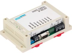
IP Relay HWg-ER02b
Ethernet relay with a full RS-232/485 converter, monutable on a DIN rail.
PortStore/PortBox
-
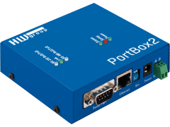
PortBox2
RS-232 and RS485 full serial port to Ethernet converter.