


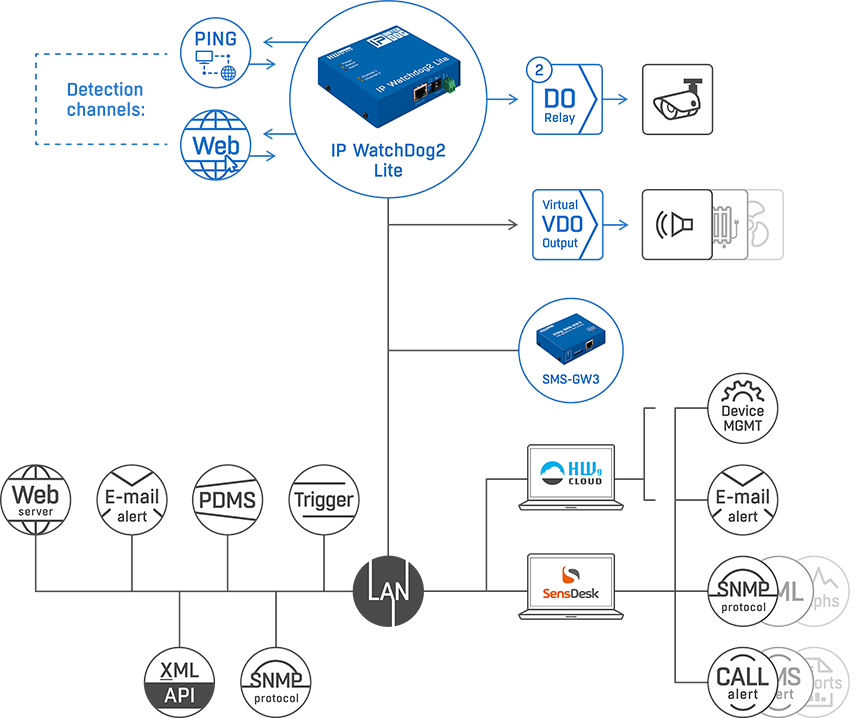
In a user-defined period, the IP WatchDog2 Lite detects the status of internet connection and LAN connected devices. IP WatchDog2 Lite monitors the availability of up to 10 devices and can reset one or two physical devices (two output channels).
In case the internet connection or any monitored device stops responding the IP WatchDog2 Lite can restart up to two connected devices via its AC 50V/0,5A (DC 30V/1A) relay DO.
A restart of each output channel can be realized also manually from the main page (under password).
A built-in web server is used for configuring.
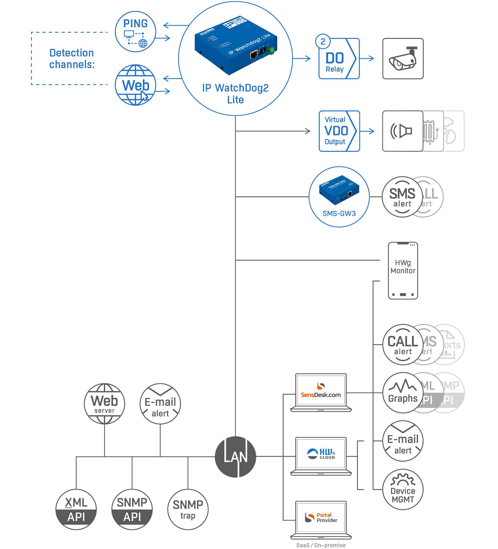
4 methods of device failure detection:
- Ping Out: IP WatchDog2 periodically sends PING requests
- Ping In: IP WatchDog2 waits for a PING from the monitored device
- Web client: IP WatchDog2 monitors the accessibility of a web page
- Web server: IP WatchDog2 waits for a request for its internal WEB page
- 10x Monitoring Channel on LAN
- 2x Relay Output AC 50V/0,5A (DC 30V/1A)
- 1x SNMP Trap; 2x E-mail; 1x "SMS+Ring" (via external GSM gateway)
- A change of monitored device status sends an alert by e-mail, SMS, SNMP Trap, or activates DO relay and a sound alarm.
- Connected via LAN. Configuration via built-in web server.
- For Ring or SMS alarm use the HWg-SMS-GW3 gateway in the same LAN.
- Data logger for up to 200 records. With the HWg-PDMS software logged data can be exported to MS Excel.
- Compatible with a range of third party SW (SCADA etc.). Examples for programmers on using the product are available in the HWg-SDK (Borland C++, MS Visual, VB, C#, PHP, JAVA and more).
Activation of a backup internet link in case the primary link fails.
Restarting irresponsive device connected to LAN.
Resetting or power cycling of remote devices.
- Routers and switches
- WiFi APs
- IP cameras
- PCs
- etc.
Who needs this product?
The IP WatchDog device replaces a human who would have to travel many kilometers or hours to a remote site in order to just flip the power switch off and on. Thanks to the "IP WatchDog", the device is power-cycled without human intervention. Often, end users don’t even notice that something wasn´t working.
- Remote restart of kiosks (manual/automatic)
- Autonomous restarting of Electrical charger units
- Keep working complex system of 3-10 different devices
- IP cameras connection verification
- Automatic start of backup LTE internet connectivity
WatchDog2 as part of the remote monitoring system
- The device can be monitored remotely over the internet using SensDesk Technology portal
- Device can be listed in HWg Monitor mobile App.
- WatchDog2 devices can be connected to HWg Windows software HWg-PDMS and HWg-Trigger.
Standalone (no portal) alerting options
- Channel can alert (send a notification) by SNMP Trap
- Channel can alert user by email (via SMTP server)
- Channel can alert user by SMS + Voice Call ring (device HWg-SMS-GW3 gateway in the same LAN is required).
Compare IP Watchdog2 Industrial and Lite
Why use the SensDesk Technology portal?
IP WatchDog2 devices can be connected to any SensDesk Technology portal:
- Free HWg-cloud.com
- paid SensDesk.com
- 3rd party Portal providers
Why to connect device to the portal:
- Portal shows a graph for each output (channel) restart
- History overview in PDF reports
- All current states in your pocket (Mobile Apps)
- Portal can alert you when device is not reachable (connected to public internet)
- Portal can inform you about local restart by
- Email from the portal
- SMS from the portal
- Voice Call from the portal
Recommended products

SensDesk.com subscription plans
SensDesk.com is a paid service with a monthly testing account. To pay SensDesk.com you can choose one of year based subscription plans.

HWg-Trigger
HWg-Trigger is a Windows software utility that alerts to a failed device (out of 10 listed), starts applications, or redirects alarms to text messages (SMS).

 or a serial port (RS-232).")
IP WatchDog2 Industrial
Industrial detector of internet connection or LAN/RS-232 connected device failure with the ability of its automated restart and notifications
